Desertcart purchases this item on your behalf and handles shipping, customs, and support to KSA.
🔗 Connect, Control, Conquer: Power your projects with precision and style!
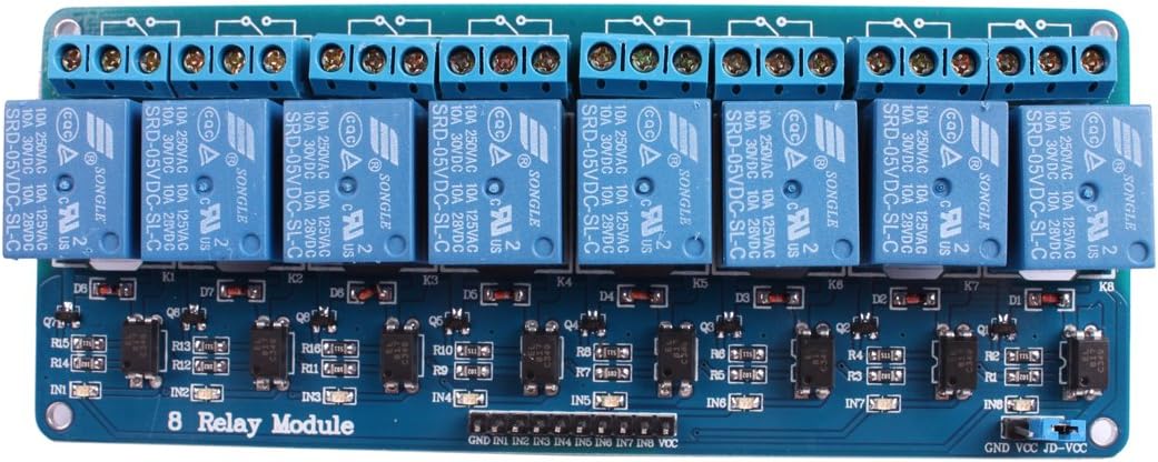
The JBtek 8 Channel DC 5V Relay Module is a robust, low-power interface board designed for seamless integration with popular microcontrollers like Arduino and Raspberry Pi. Supporting high current loads up to 10A and featuring LED status indicators, it empowers professionals and hobbyists to automate appliances and electronics with reliable, real-time control.
| ASIN | B00KTELP3I |
| Best Sellers Rank | #81,266 in Industrial & Scientific ( See Top 100 in Industrial & Scientific ) #59 in Electromechanical Relays |
| Brand | JBtek |
| Brand Name | JBtek |
| Coil Voltage | 5 volts |
| Connector Type | Through Hole |
| Contact Current Rating | 10 A |
| Contact Material | Silver |
| Contact Type | Normally Open |
| Current Rating | 10 A |
| Customer Reviews | 4.5 out of 5 stars 507 Reviews |
| Manufacturer | JBtek |
| Maximum Switching Current | 10 A |
| Maximum Switching Voltage | 250 volts |
| Minimum Switching Voltage | 5 volts_of_direct_current |
| Model | FBA_pcb board |
| Mounting Type | PCB Mount |
| Operation Mode | Automatic |
| Part Number | FBA_pcb board |
| UPC | 520361134546 |
| Unit Count | 1 Count |
| Wattage | 50 watts |
S**Y
This board works great on my Raspberry Pi 2
This board works great on my Raspberry Pi 2. I used 8 GPIO pins as relay control lines (LOW = relay on, HIGH = relay off) and made a simple Christmas light controller box, driven by the free LightshowPi program. (Basically, a glorified "color organ" for those old enough to get the reference!) It is an excellent value for the money. This board has one 10-pin header for GND/VCC and In1-In8, and a three-pin header for GND/VCC/JD-VCC. As delivered there is only one removable jumper on the entire board, and it connects the three-pin connector's "VCC" and "JD-VCC" pins. To control this board's relays using GPIO pins on a Raspberry Pi 2, remove this jumper, supply 3.3 volts to that previously-jumpered "VCC" pin, and supply 5 volts to that previously-jumpered "JD-VCC" pin. The "JD-VCC" pin feeds the 5 volt relays' coils, and the "VCC" pin supplies the reference voltage to the relay control logic that In1-In8 use to sense when these lines are grounded, triggering their relay.
S**R
Works with "ST Nucleo F411RE" and "Raspberry Pi Model 2 B V 1.1"
I purchased this relay module to do some prototyping. It has worked well with the boards I have in house at the moment: * Raspberry Pi Model 2 B V 1.1 * ST Nucleo F411RE. Both of these have 3.3V GPIO pins, but the array worked fine when wired correctly. Please keep in mind the maximum current your micro-controller can drive. Both the PI and the Nucleo can operate a few of the relays, but you'll probably need a separate 5V supply to operate all 8. There are a number of good tutorials on how to utilize a relay array with the pi. There's a little less documentation for the nucleo 411 RE, still everything worked on the first try. I wired the following pins from the relay board to the pins in the CN7 connector on the nucleo: * VCC to pin 18 (+5V) * GND to pin 22 (GND) * IN1 to pin 17 (aka PA_15) * IN2 to pin 15 (aka PA_14) * IN3 to pin 13 (aka PA_13) Then I wrote the following code: #include "mbed.h" DigitalOut myled(LED1); DigitalOut relay1(PA_15, 1); //high is off DigitalOut relay2(PA_14, 1); DigitalOut relay3(PA_13, 1); int main() { set_time(1436486851); while(1) { time_t seconds = time(NULL); myled = !myled; relay1 = (seconds % 3 == 0 ? 0 : 1); relay2 = (seconds % 3 == 1 ? 0 : 1); relay3 = (seconds % 3 == 2 ? 0 : 1); wait(1); } } Sure enough, the nucleo kept 1 out of the 3 relays I had wired on each second, and cycled between them.
B**K
Sprinkler upgrade
Had an orbit sprinkler system with a "wireless" remote. It was wireless but only up to about 6' away. Probably rf interference from wifi, but didn't care to fix it. Built a much better controller, using opensprinkler running on an rpi zero w. Mounted everything to an old tiny cutting board and mounted to the wall. Used these to control the valves. They're running 24VAC and have been working great for a week now. I left the VCC / JD-VCC jumper connected and just used the power from the pi's 5v out to power 2 of these. Seems sufficient for my needs. When I move to automating Christmas lights, I'll probably look to these relays again.
J**.
Can somebody say "AWESOME!" ?!?!?!?!?
What a deal! Unless you already have the components lying around, you can't build an 8 relay control board for this price. Everything about this unit is solid. Super easy to control using wiringpi library from http://wiringpi.com/ Each relay has it's own LED so you will know what is going on. The off state might be confusing to some new hardware hackers. When the unit is powered off, the relays are in the same state as when no voltage or a POSITIVE voltage are sent to the input pins. You send a 0 bit ( -5v ) to the pin to actuate the relay. If you are using resistors to force an off state you want to use PULL UP resistors to maintain the +5v needed to keep the relays off until you want to turn them on.
D**Z
works well
some simple connection instructions would have been useful, even if just a link to a web page with good diagrams. I am using mine to drive the lights of an outdoor replica of a German train signal. I am driving it with an ESP8266 which has 3.3V outputs. I was however advised to provide 5V to both the VCC pin next to the inputs and also to the JD-VCC pin for the coil relays. This is easy to do with a single 5V power source which can power the ESP8266 and the relay board as shown in the diagram. Note the GND pin next to the inputs should be left unconnected in this configuration. I was surprised that I could feel some warmth on the relays that are on. Note that the relay board (in this configuration) does hold the pins high on power up, so one cannot use pin D8 on as an input as the ESP8266 will not boot. I switched to using D3 instead of that pin. Each coil seems to draw just 60mA when on and the IN pins draw just 0.047mA each. I would buy this again next time I need a big bunch of relay outputs for switching AC power.
T**L
Works great with Raspberry Pi and Falcon Player Plus!
Works perfectly with Raspberry Pi3!! The logic circuits are 3.3v so it can be directly connected to the GPIO outputs! I am using an external 5v power supply to feed the relays as the RasClock takes up the 5v outputs on my Pi header. This board does include a jumper on the power header that I imagine is to jump the 3.3v from the Pi to the 5v input to drive the relays but I have not tried this so can't say if 3.3v is enough to drive the 5v relays (nor of the current draw would be too much for the Pi under that setup). Pin outs: Main header: - GND - Pi ground - VCC - Pi 3.3v - 1-8 - Pi GPIO outputs Power header: - JD-VCC - 5 volts in for relay power - GND - relay ground (this is tied to GND on the main header as well) - VCC - 3.3v in/out (this is tied to VCC on the main header and carries 3.3v to power the logic circuits).
K**G
Clacky, but awesome switching for an Arduino (or other real time processor)
This is an array of eight little relays capable of controlling AC or DC current and perfect for small battery projects as well as for use with 110V or 220V line current. (Check the specifications and your comfort level if you are planning to control higher voltages though.) Each relay is controlled by a single line from the Arduino and has connectors for normally open or normally closed. The board also needs a ground and 5V VCC hookup. These can come from the Arduino. (I don't know if they'll work with 3.3V logic levels, probably not.) I've been using this array to control AC electroluminescent (EL) wires, and they work well. They are a bit noisy, but the relay clacking sound effects are what I want for the project. So far, I've only tested the relays with a 100ms delay, and they work fine. Since they are mechanical, I assume that there is some top speed. If you want to do 5ms switching, odds are you should get a board with TRIACs like the Sparkfun EL Sequencer or roll your own.
I**Y
Good relay board
This 8 channel relay board works as expected. Note in order to take advantage of the isolators, you need a separate 5V dc power supply. In my application that was most certainly required. Otherwise the back EMF and or noise was coupled back to the Arduino and would crash it. An important thing to note is the connections on the bottom are exposed. If you are using AC, you must insulate them. In my case, the case that this went into does that. If not, its seriously dangerous to have exposed mains AC. DC is less of a concern if its low voltage low amperage. Still I would insulate either way.
M**D
Excellent
Well make,, I give 4 stars due to many pins were bended so I had to adjust, luckily not broken. but in general the product is great.
S**.
Bed products all relay is not work
Not good
Trustpilot
3 days ago
2 weeks ago